Join 3000+ companies who work with Yijin Solution


As-Cut (ISO 9013 Range 3-5)

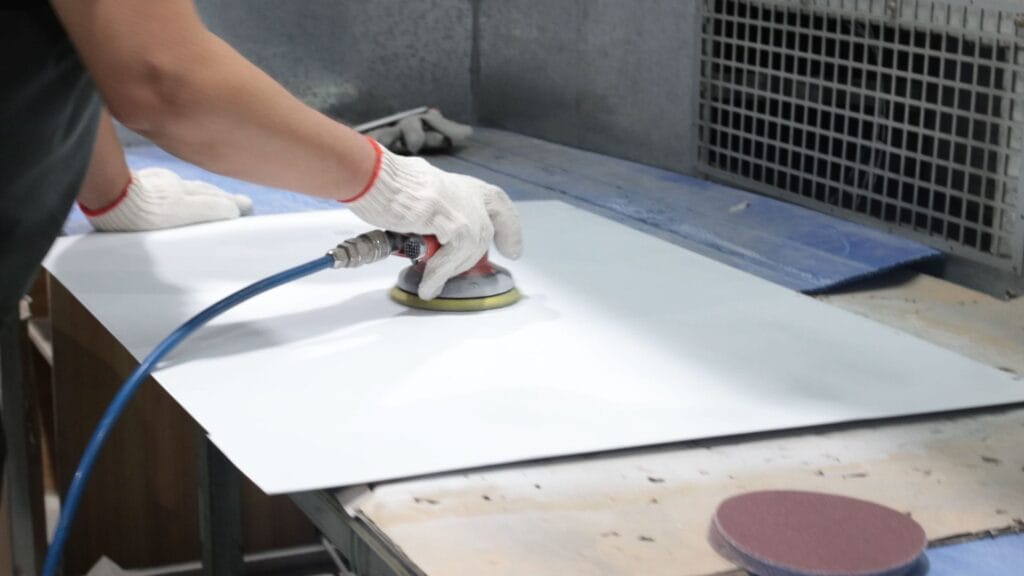
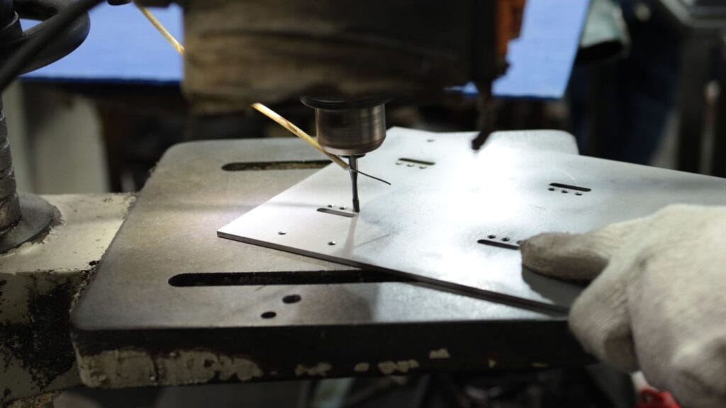
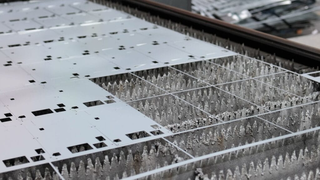
Deburring and Slag Removal

HD Plasma Edge (Range 2-3)

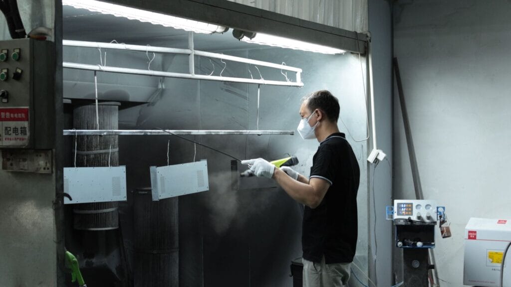
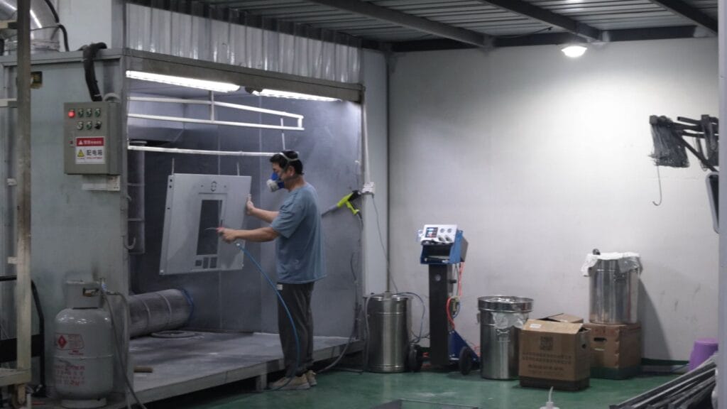
Powder Coating

Hot-Dip Galvanizing and Plating

Passivation and Pickling
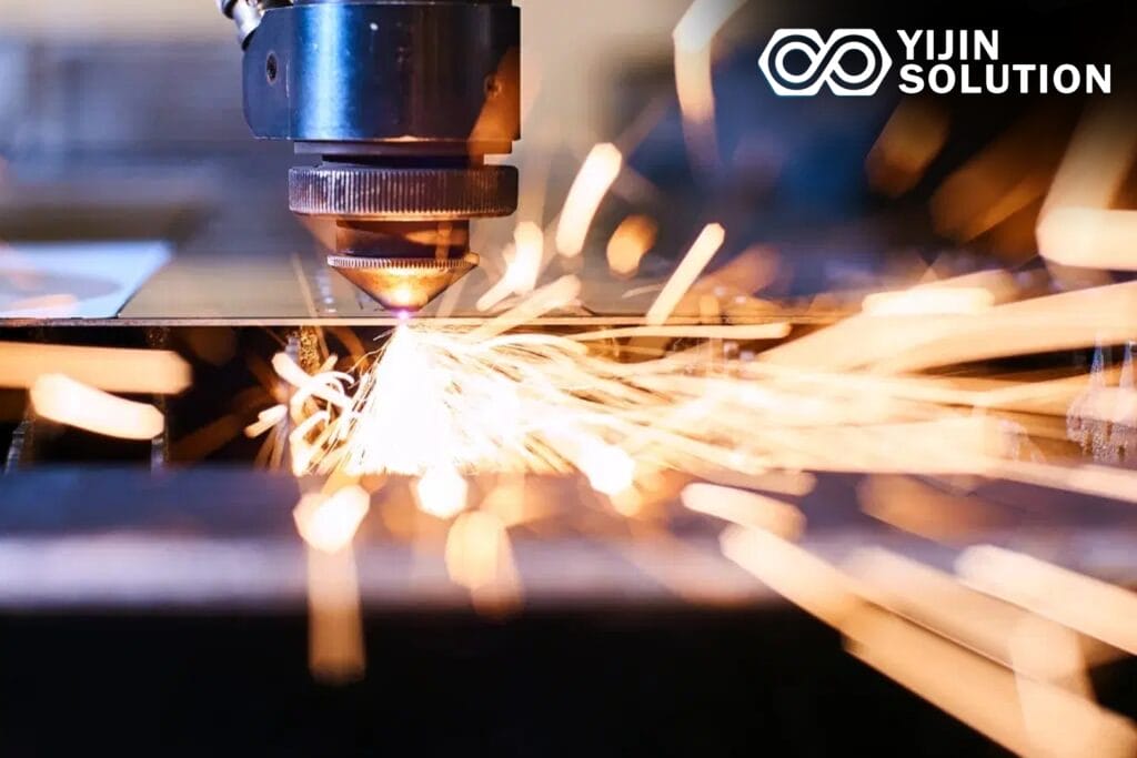
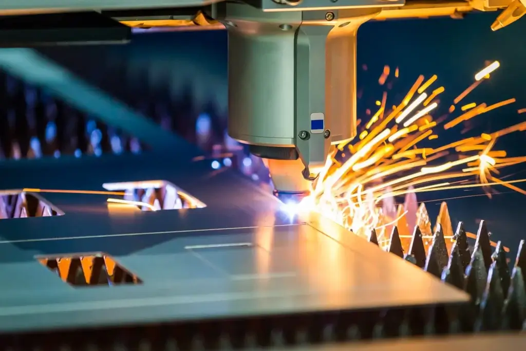
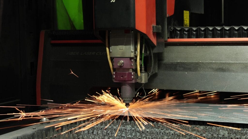
Conventional Plasma Cutting
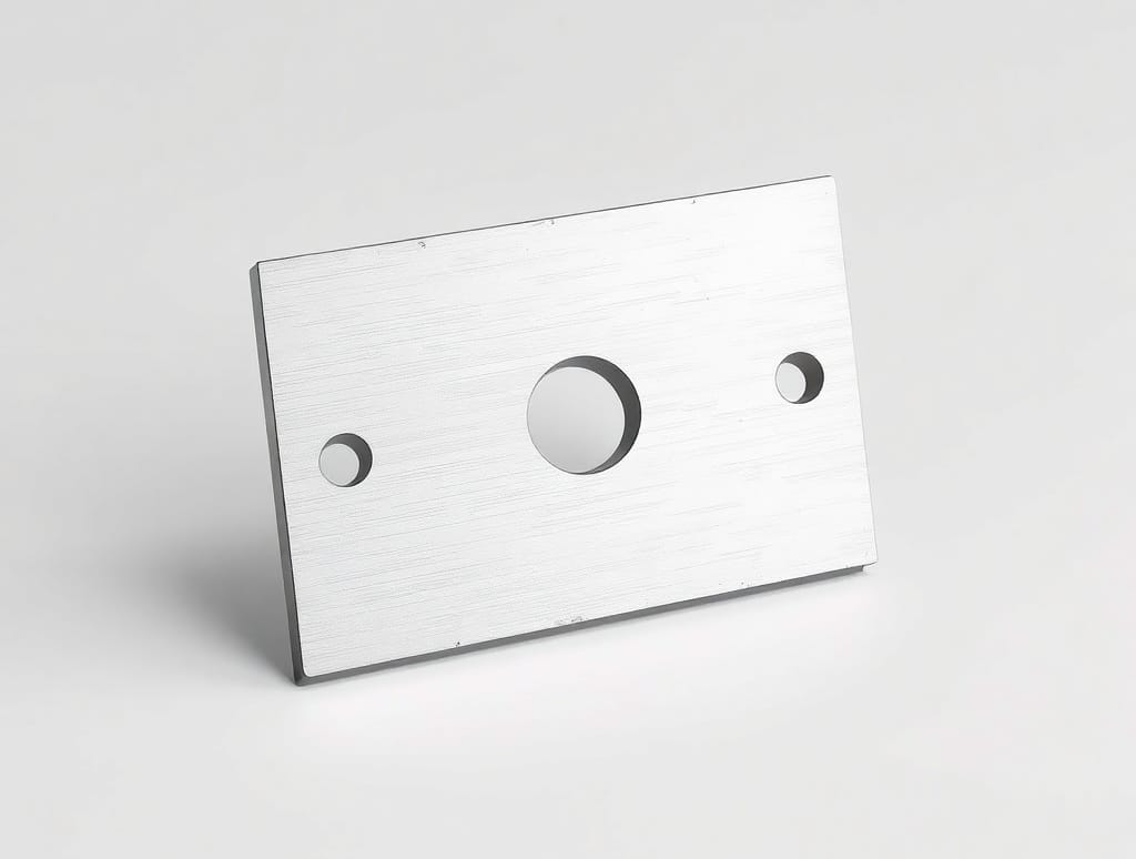
Compressed air or nitrogen plasma at 30 to 200 amperes, cutting carbon steel, stainless, and aluminum from 1 to 50 mm thick. Kerf width 2.5 to 5 mm with a moderate bevel angle on the cut face. The cost leader for structural blanks, gussets, brackets, and parts where edge quality is secondary to throughput.
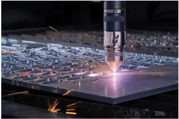
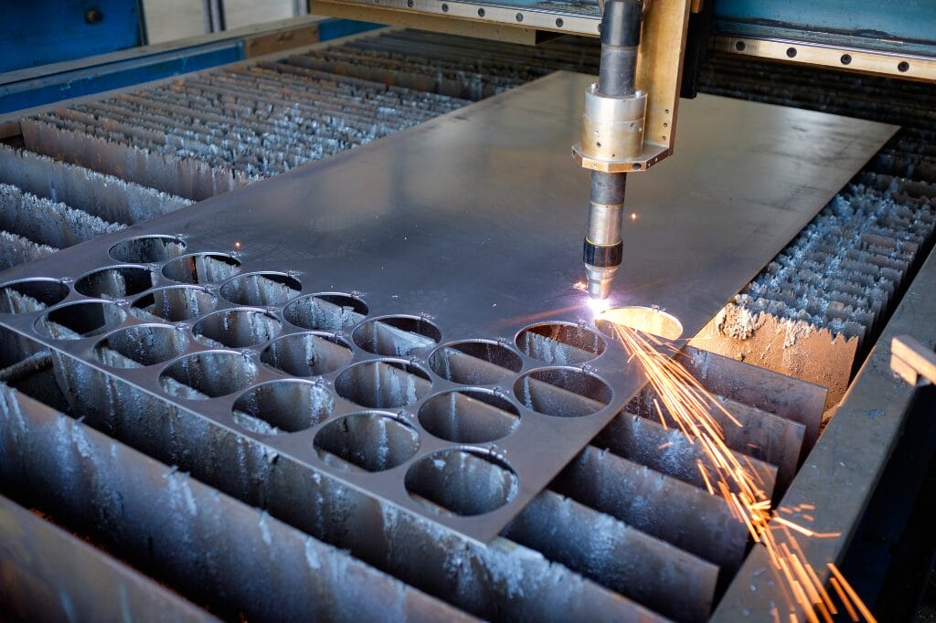
High-Definition (HD) Plasma Cutting
Constricted nozzle and oxygen or argon-hydrogen gas mix at 30 to 130 amperes, producing a tighter arc and a near-square cut edge. Holds ±0.2 mm tolerance and Range 2-3 edge quality on plate up to 25 mm, approaching fiber laser quality at lower equipment cost. The right choice for visible parts and weld-prep edges that would otherwise need machining.
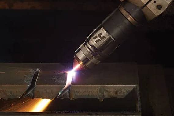
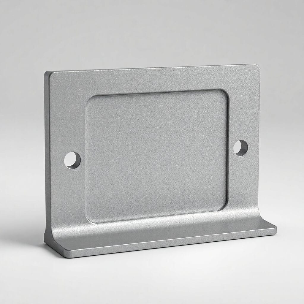
Bevel and 5-Axis Plasma Cutting
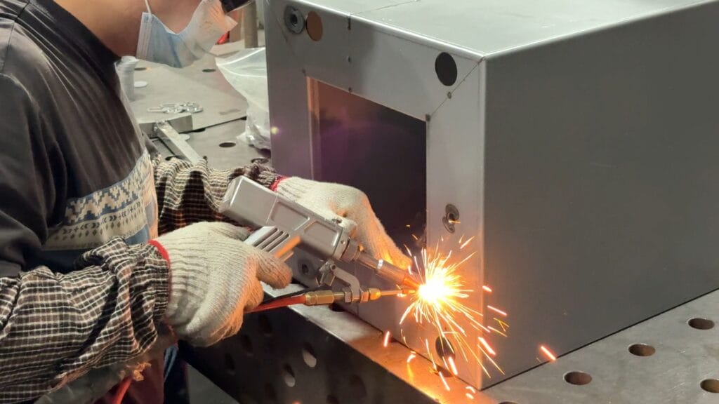
A 5-axis plasma head that tilts the torch during the cut to produce V, X, Y, and K-grooves for weld preparation in one operation. Eliminates a secondary milling or grinding step on thick-plate weldments. Used for pressure-vessel components, structural fabrications, shipbuilding, and any plate over 15 mm where the next operation is welding.

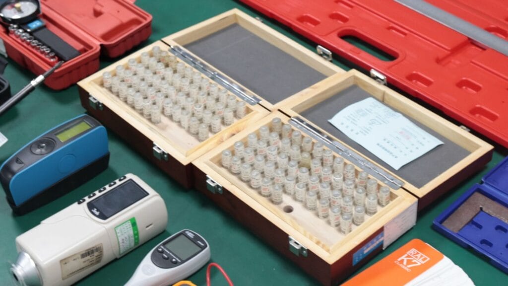
Zeiss CMMs, laser interferometers, and optical comparators verify every critical batch. Parts hold ±0.05 mm typical and ±0.02 mm on 5-axis programs. First Article Inspection and PPAP Level 3 documentation are standard on production runs.

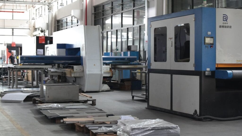
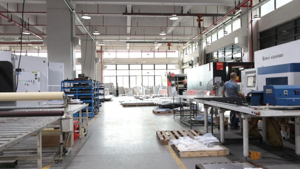
Prototypes ship in 3 to 7 business days and production shipments in 2 to 4 weeks. Plasma tables plus in-house deburring, bending, and welding keep parts moving without supplier handoffs.

Single-piece prototypes and production runs of 100,000+ parts go through the same machines and the same inspection standards. No minimum order quantity. Volume does not change quality gates.

Your prototype and production parts come off the same tables with the same program. No re-qualification, no new vendor onboarding, and no process variation when you scale from validation to volume.

Carbon steel up to 80 mm, stainless to 50 mm, aluminum to 40 mm. Bevel-cut weld preparation in one operation. Plasma covers thickness ranges where laser is too slow and waterjet costs too much per part.

Direct factory pricing without broker margins. Our engineering team reviews your drawing before programming starts to identify nesting, common-line cutting, and lead-in optimizations that reduce cycle time and per-part cost.
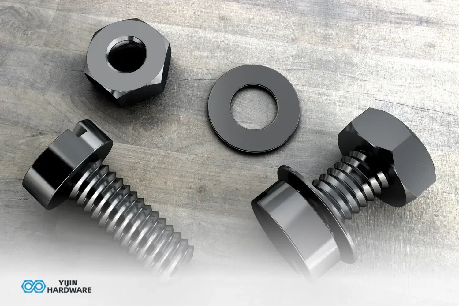
Types of Mechanical Threads
Threads are basically helical ridges that get machined onto cylindrical or conical surfaces. They’re pretty ingenious – they convert rotational
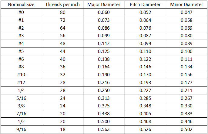
Complete Thread Size Chart Guide: Understanding All Standards and Applications
Threaded components have accurate specifications for assembly integrity and performance. We have put together this thread size chart to help
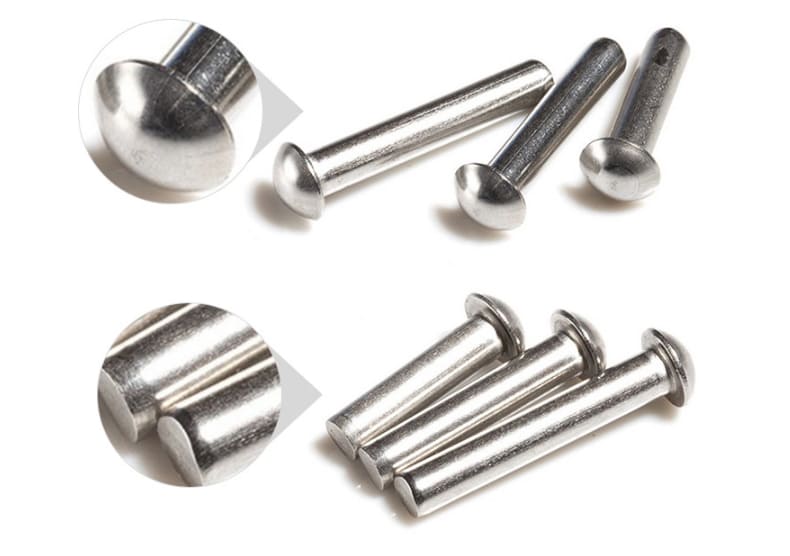
Types of Rivets And Their Applications
Rivets are permanent mechanical fasteners used to join materials. Common types include solid, blind, tubular, split, shoulder, drive, self-piercing, and