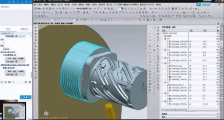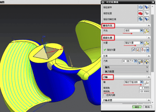
Five-axis programming core three parameters: drive method, projection vector, and knife axis.
Driving method: The common methods include streamline (more intelligent), surface (set cutting direction, step moment, cutting mode, and other parameters), boundary, etc. After the driving method is determined, the driving geometry is selected, and the driving geometry is used to generate the first “virtual tool path”, and the rationality of the tool path is observed, and then the optimization is done.
Projection vector: Discusses how the virtual tool path is projected onto the workpiece geometry after it is first generated. The projection affects the quality of the final tool path on the workpiece surface but has nothing to do with tool attitude. If the projection is not correct, the tool path will show confusion such as zigzag lines.
Generally speaking, the projection vector options are less, often selected, knife axis (knife path along the direction of the knife axis projection tool surface), vertical driver (driving geometry), and specified vector, the above projection principle is simple to understand, and easy to operate.
Tool axis: discuss the processing, the tool in what attitude in the final knife path “walk”, tool attitude can be divided into a fixed tool axis, an axial change, two axial changes, etc., there are many options for the tool axis, the following is classified.
Away from the straight line, the application of open area surface or rotary surface, each path of the tool attitude has a direction change, the tool attitude to a straight line, with the change of processing direction, the path of the tool. This approach is limited if there is artifact interference.
Away from the point, it is best to use a closed area, each path of the tool posture has two direction changes, and the attitude change is large, this method will have limitations.
Vertical drive, depending on the choice of the situation, generates the tool will always vertically the gesture of dao road, if it is a straight bevel, tool posture and fixed knife road and tidy, if it is a curved surface, cutting tool posture will change at any time, and cannot be specified tilting Angle, interference occurs if the cutting tool and workpiece structure, unable to adjust the cutter attitude, this method will be limited.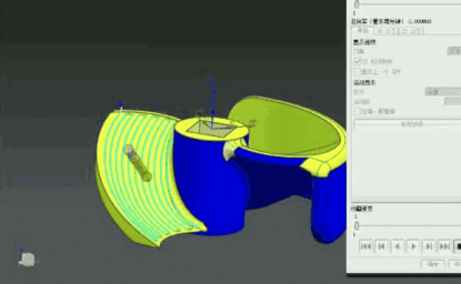
Compared with the driver body, it is more flexible than the vertical driver body. If the machining surface is curved, the posture of the tool during machining will change at any time, and the roll Angle can be specified.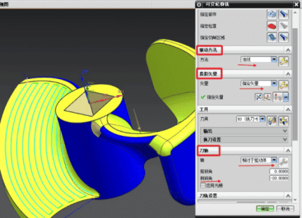
4 axis, perpendicular to the driver/relative to the driver, the application of closed areas such as the structure of the rotary body, generates the whole cycle movement of the knife path, and can change the roll Angle, rake Angle, etc., this method is simple and convenient.
Drive side blade, the use of oblique cutting tool side blade inclined wall, side edge direction is designated as “upward (purpose is to make the cutter attitude up), if the wall is straight bevel, cutter profile is changeless, wall surface, cutting tool processing attitude will change, at the same time, you can specify a tilting Angle to continue to change the posture, the method is relatively flexible.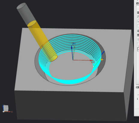
Profile milling, used to mill the inclined straight wall, using the known bottom surface, automatically finds out the inclined wall to be processed. Can not mill surface (milling surface with side edge drive), and side edge drive is very similar to the generation of plane milling is similar to a single knife path, but can use the transformation out of multiple knife paths.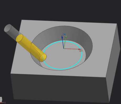
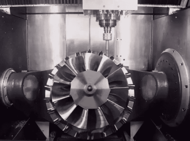
Finally, multi-axis programming is mainly based on the surface structure of the workpiece and processing requirements, with the model of a five-axis machine tool, avoiding interference with the workpiece, optimizing the tool posture, and reasonably generating the machining tool path. Programming itself is not difficult to master, but processing technology requirements are high.